If you have a little enthusiasm about electronics, you have often heard about resistors, capacitors, diodes, etc. But did you ever think about their classification, function, symbol and use? Here we discussed in a detailed manner about these basic circuit elements.
What are the basic circuit elements?
An electrical circuit is defined as a complete path for electrical current flow. These electric circuits consisting of resistors, capacitors, inductors, vacuum tube devices, voltage and current sources.
Each circuit component such as a resistor, capacitor, inductor, diode etc. is called basic circuit elements. 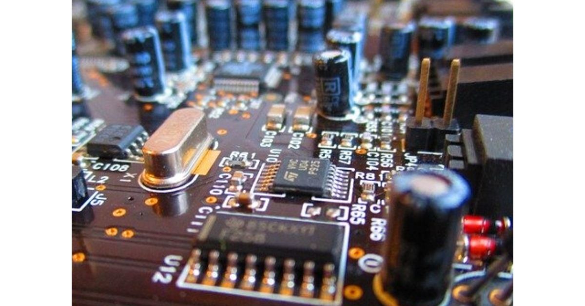
Types
1. According to port number
This classification is based on the number of terminals they have to connect with other components.
One port element
These elements have only two terminals to connect with other elements. Resistors, capacitors, diodes etc are the example of one port element.
Multi port elements
These elements have more than two terminals to connect with other elements. Transformers have six terminals so it is a multiport element. Two-port elements having four terminals are the most common multiple port element.
2. According to ac amplification/rectification power
Active or non-linear elements
Diode, transistor etc can amplify/rectify the ac power. Thus they are called active elements.
As the current-voltage relationship is not linear in case of a diode and transistor, they are also called non-linear elements. Ohm’s law and Kirchhoff’s law do not apply to the circuits consisting of non-linear elements.
Passive or linear elements
Resistors, Capacitors and Inductors can not amplify or rectify ac power. Thus, they are called passive elements.
As the current-voltage relationship is linear in case of resistor, capacitor and inductor, they are also called linear elements. Ohm’s law and Kirchhoff’s law apply to the circuits consisting of linear elements.
Some basic circuit elements
RESISTOR
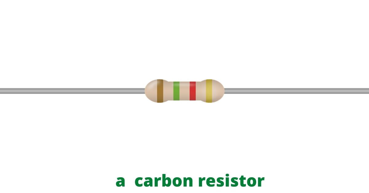
Resistors are the most commonly used circuit elements. As the name suggests resistors generally resist the current flow through a circuit.
Current-voltage relationship
Resistor is a linear element meaning its current is linearly increasing or decreasing with the increase or decrease of voltage. Current-voltage relation defined as-f(V, I) =0
Resistors follow Ohm’s law,
V=i×R; where ‘V’ is the potential difference, ‘i’ is the current through the circuit, and ‘R’ is the resistance.
Power as a function of resistance: Power,

Unit
The SI unit of resistance is ‘Ohm‘
symbol: ‘Ω’
- The resistance between two terminals of a conductor when a fixed potential difference of 1 volt is applied to these terminals that produce a current of one ampere in a circuit is termed as 1 ohm.
Dimension: Kg.m2.s-3.A-2
Colour code
Colour-code is a standard way to define the resistance of a resistor only by seeing the colour bands on its body.
Use:
- Small carbon resistors with power rating 2W or less are mostly used in common electric circuits.Wirewound resistors are used in low resistance high power applications.
- Small variable resistors also called potentiometers or pots are generally used in circuits to regulate current and voltage.
CAPACITOR
A capacitor is used to store the electric charge and release it when desired. Different types of capacitors are used in electric circuits.

Mechanism
A capacitor offers very high impedance to dc but very low impedance to ac. Capacitors used in this way are called blocking capacitors.
Another way to use a capacitor is the bypass capacitor. Here a capacitor is connected parallelly to a large resistance. It bypasses the ac that flows through the resistor.
Types
The capacitors are named according to the use of dielectric inside it. There are various types of capacitors like plastic, polystyrene, paper, mica, ceramic and electrolytic capacitors.
Polarity
Capacitors are always manufactured and used considering the polarity. They always have ‘+’ and ‘-‘ signs on them. A small fresh capacitor has come to the market with a longer wire in the positive side than the other side. Capacitors are connected with circuit boards or with other components very carefully otherwise it can be fatal.
Current-voltage relationship
For a capacitor current-voltage relationship is given by,
f(V, Q)=0

Meaning, current= capacitance×time rate of change of potential difference.
Unit
The SI unit of capacitance is ‘farad’.
- ‘1 farad‘ is defined as the capacitance of a capacitor when charged with 1 coulomb of electric charge, has a potential difference of 1 volt between its plates.
Symbol: ‘F’
Dimension: s4.A2.m-2.kg-1
Use
- Capacitors are used both for ac and dc voltages. They are used to store and discharge the electric charge.
- Variable capacitors like air capacitors are used as tuning capacitors in radio receivers and ganged capacitors in audio oscillators.
INDUCTOR
Inductors are basically coils of wire that can produce an induced voltage in it when the current through it varies with time. 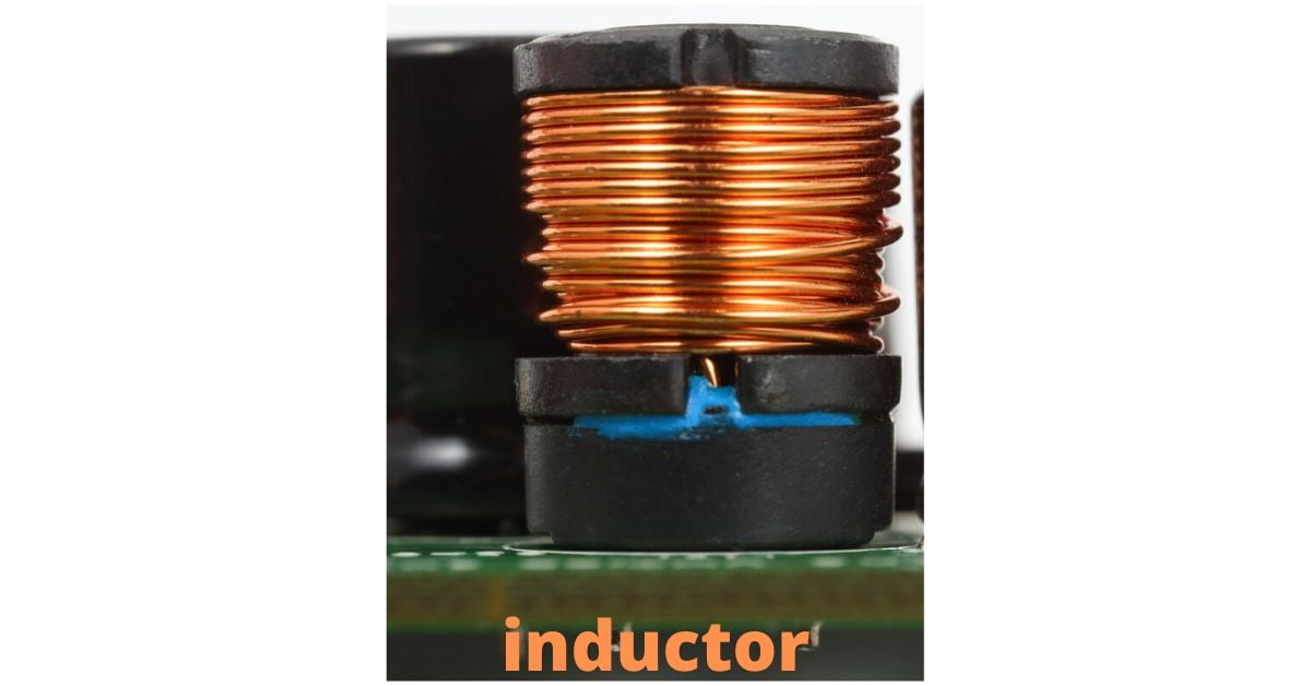
Current-voltage relationship
For an inductor current-voltage relationship is given by,
f(Φ,i)=0

Unit
The SI unit of Inductance is ‘Henry‘.
- ‘1 Henry’ is defined as follows- when an electric current, changing at one ampere per second results in an electromotive force of one volt across the inductor.
Symbol: ‘H’
Dimension: ML2T-2I-2
Use
Inductors, that have a large value of inductance are called choke coil.
- Choke coil offers very low impedance to dc but very high impedance to ac. Therefore, chokes are used to filter out ac components from a mixture of ac and dc.
- Iron cored are used for Audio frequencies, this type of chokes are called Audio-frequency chokes(AFCs).
- Air-cored chokes are used for radio frequencies, this type of chokes are called Radio-frequency chokes (RFCs).
DIODE
Diode is an active, non-linear device also comes under the Basic Circuit Elements. The device is called “diode” as it has two (‘di’) electrodes. We often call it ‘Diode valve’ in an analogy that current always flows through it in one direction. 
For further information about diode and other vacuum tubes please read our separate post on ‘vacuum tubes‘.
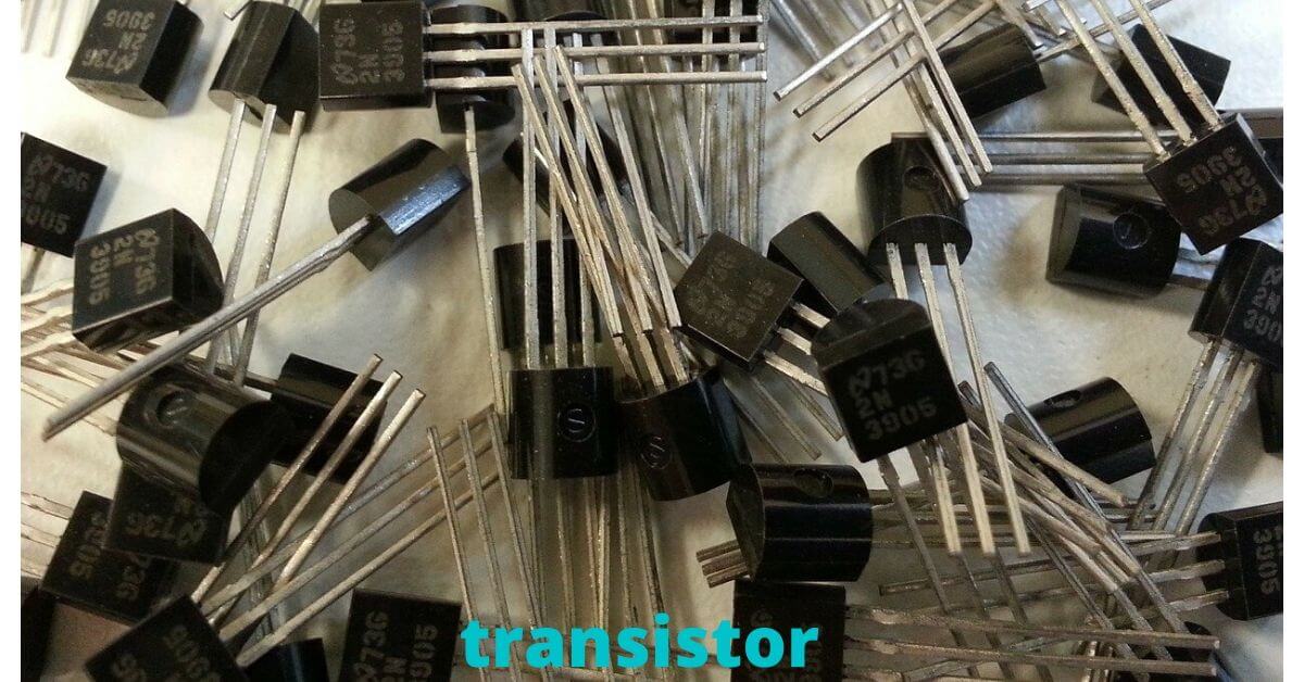
TRANSISTOR
Transistor is also an active, non-linear element. It is a semiconductor device that uses either to amplify or switch the electrical signal.
Types
There are different types of transistors like BJT, MOSFET, FET, NPN OR PNP etc according to their structure, polarisation, semiconductor material, application etc.
Use
- Transistors are used to amplify electrical signals.
- Transistors are also used as switches to on/off an electrical circuit.
If you have any query regarding “Basic Circuit Eelments” please comment below. We will try our best to answer. Thank you.
What are the basic circuit elements/components?
Each circuit component such as a resistor, capacitor, inductor, diode etc. is called basic circuit element.
What is active circuit element?
Diode, transistor etc can amplify/rectify the ac power. Thus they are called active elements.
What is passive or linear elements?
Resistors, Capacitors and Inductors can not amplify or rectify ac power. Thus, they are called passive elements.

